|
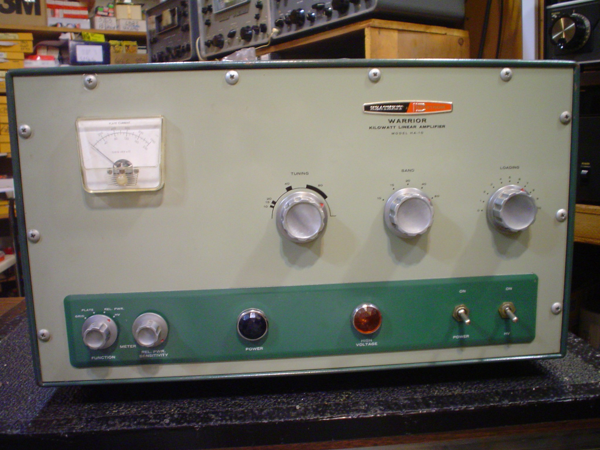
The Heathkit Warrior is an Ameritron AL-811H on steroids. Pay no attention
to the unfair negative press this fine piece of vintage gear has received
from those less knowledgeable.
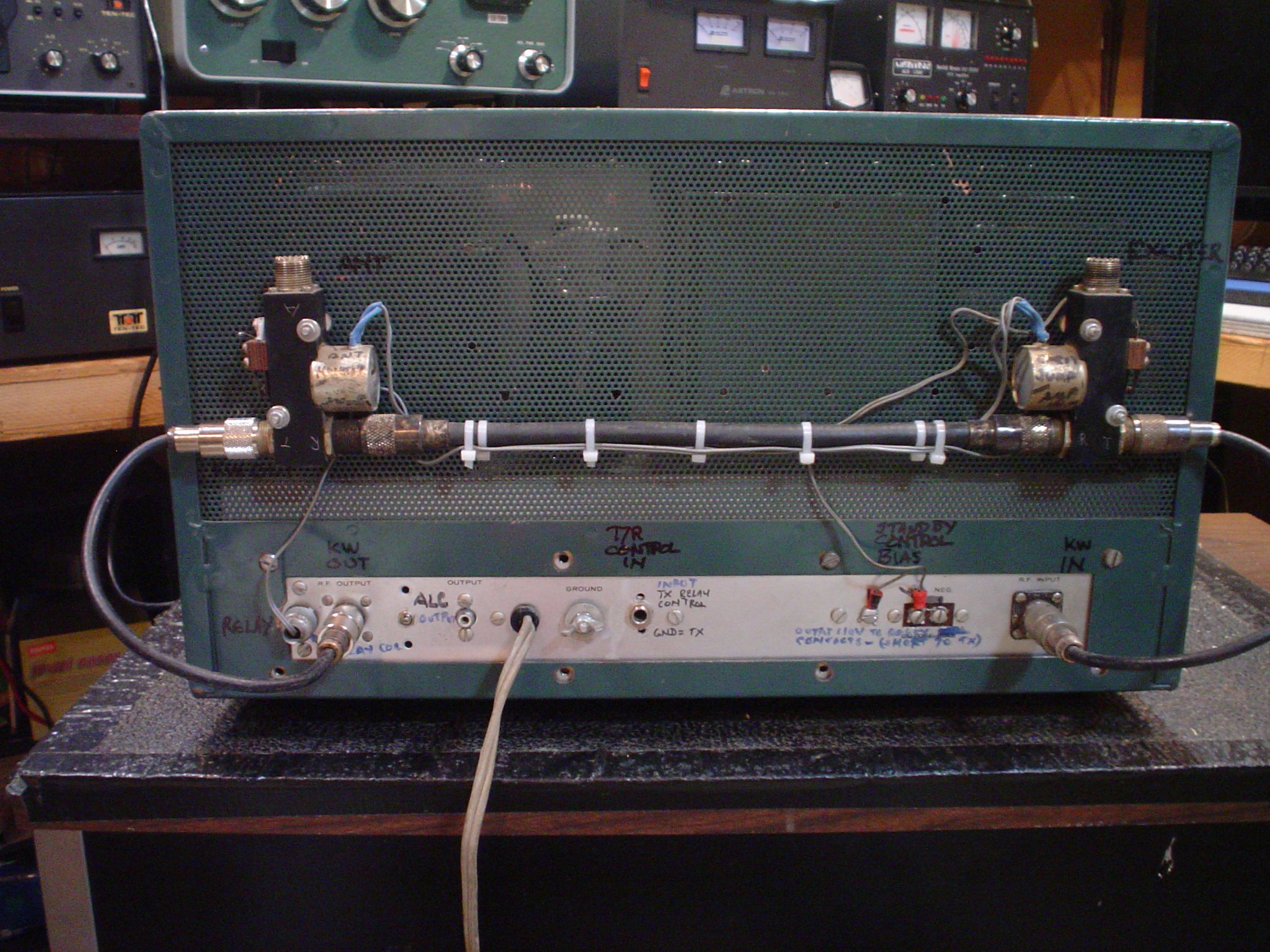
It is true that you will have to add T/R switching for a modern
transceiver. I will post a schematic here later to show you how to do it.
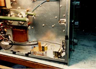
The photos show the Dow Key relays I used to switch the RF. The auxiliary
contacts on one of the relays also switch the cutoff bias that shuts down
the 811As during receive. You can use modern relays to do this switching
and mount them inside the cabinet. I have done up half a dozen of these
over the years. The slick thing about the Dow Key relays auxiliary contacts
on this one is the sequencing. All contacts for the RF are closed on
transmit mode before the -100VDC negative cutoff bias is set to the normal
-6VDC operating bias. This prevents any zorches on transmit due to no load
on the amplifier. Furthermore, it is necessary to have these switch through
relays to prevent the condition of drive reaching the grids with no plate
voltage on. If this occurs, instant destruction of the 811As will occur due
to excessive grid current. The plate supply MUST be ON in order to close
the relays allowing drive to the amp. If the plate supply is off, the
relays just pass the exciter through to the antenna to run in barefoot
mode. This is the same as some amps which have a STANDBY mode, which allows
for filaments to heat up or run barefoot.
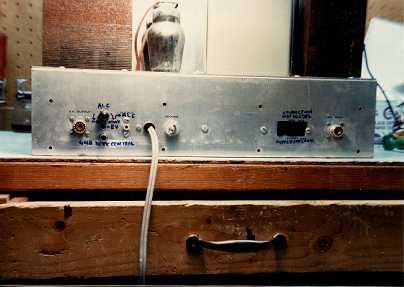
I also include a negative voltage adjustable ALC circuit which is totally
fool proof if you have the amp correctly tuned. It is derived from a plate
current sampled across a resistor. It will NOT protect the amp from
excessive grid current. Be sure to read the specs of YOUR exciter or
transceiver to see if it is compatible. Some rigs expect no more than 4
volts negative. You might want to include a zener diode to clamp it or some
other means to protect it. This circuit worked nicely with a SB102 and a
SB104 though. Adjust everything for proper operation first. Then increase
the ALC pot til the output just begins to drop. At that point, the amp
input power will not increase even if you set off dynamite in front of the
mike.
PARASITIC SUPPRESSORS RESISTOR FAILURE
See my discussion on the SB200 for details on the 47 Ohm carbon resistors
in the plate parasitic suppressors. If the amp has been used extensively on
10 meters, they may have overheated. DO NOT USE MODERN FILM RESISTORS! They
are inductive and the amplifier will oscillate!
KEEP A LOAD ON THE INPUT AND OUTPUT
When initially testing the amplifier, be sure to have a dummy load of
appropriate wattage connected to the output. Also, put a 50 Ohm non
inductive load across the INPUT as well; this one does not have to be high
wattage. This will get you past the initial test to see if the high voltage
comes up.
Be sure the bias supply electrolytic capacitor does not have a pimple on it
indicating impending failure. This can be tested with only the filaments
on, no high voltage. Compare bias voltage with Heathkit manual
troubleshooting charts to see if it is good. Also, if negative cutoff bias
of about -100VDC is provided, check that too. I always build this cutoff
bias into the amplifier rather than getting it from the exciter, even
though that was the practice in the old days. That way if the exciter is
turned off or disconnected, the amplifier is prevented from oscillation due
to the high negative bias.
The good news: the high voltage supply has an old fashioned oil filled
condenser, not electrolytic capacitors which need to be periodically
replaced, like the SB200 and modern amps use. This filter condenser will
still be good when your grandchildren are using your radios.
HIGH VOLTAGE POWER SUPPLIES AND THE BANE OF 866 RECTIFIERS
I've now written an entire article about why you should not use 866 rectifiers. Please click the link for more information.
THE INFAMOUS ARC IN THE WARRIOR FILTER CHOKE DEBUNKED
While we are on the subject of the power supply, disregard all the urban
legends about the filter reactor (choke) failure. It is all BS! People hear
a nasty rattling noise when the swinging choke laminations vibrate at a 120
cycle rate. I got this amp for next to nothing because the seller thought
he had an arc. Use your head. Did the fuses blow? Did the mercury vapor
rectifiers flash over? Well there isn't a short, it is just making noise!
I have fixed this problem before by removing the filter choke from the
amplifier, cleaning up the laminations and fish paper spacer for the air
gap (necessary in a swinging choke) and reassembling the choke. I then put
the choke partially submerged in good spar varnish in a standard aluminum
pie pan. I heat the oven up to minimum temperature, maybe 90 degrees F
measured with a good thermometer (not the oven dial) and turn off the oven.
I then put the choke and pie pan in overnight. Or you can put it behind
your wood stove and let it sit for a day. Take it out of the heat and let
it cure for a few days to let the varnish harden.
I was in a hurry on this one. I put a small block of wood on the outside of
the choke over the rattling laminations. Hopefully the kit builder oriented
the choke so the small straight part of the lamination is on the outer side
of the amplifier. Then I put some stainless steel hose clamps around the
choke and wood piece and carefully and evenly draw down the tension just
enough to shut up the vibrations. The block of wood prevents the hose
clamps from contacting the core and shunting the magnetic field. Do not
leave out the block of wood or you will screw up the inductance. If it gets
noisy again, just tighten the clamp a quarter of a turn. All fixed.
811A TUBE POWER RATINGS AND THE BS YOU HEAR ABOUT IT
The 811A was a ground breaking tube invented by CBS around WW2. It still
makes a nice modulator tube in class B service. But that is for AUDIO
ratings. Then we started running them on RF. For SSB, that is not bad. The
Heathkit Warrior manual is wrong on the ratings for RTTY and AM linear use.
The plate current shown in the manual WILL DEFINITELY MELT A HOLE IN THE
PLATE THE FIRST TIME YOU USE IT AT THE PUBLISHED VALUES OF PLATE CURRENT.
Ameritron also runs them hard also in their AL811 and AL811H (the four tube
model).
If 811As are run over their ICAS ratings for any time (AM and RTTY), the
plate material will be damaged. This is evidenced by a silvery appearance
to the normally dark gray in the center area of the plate structure. In
severe cases, you will see some which have a dime sized hole burned in the
plate. The glass envelope may be sucked in and vacuum lost, which causes
high voltage arcs. The RCA Transmitting Tube Manual TT-4 says: "Plate shows
NO COLOR when tube is operated at maximum CCS ratings, and shows a barely
perceptible red color at maximum ICAS ratings." This means in a very dark
room and no pilot lights inside the equipment you look at the plate and you
are not really sure if it is red or not. If you see clearly a red cast to
the 811A, you are running it too hot; back off. In a transmitter with four
paralleled tubes, the tube characteristic match and the stray capacitance
that influences grid drive and plate load sharing is also not exact. Even
with a precision matched set of tubes, stray capacitance inherent in the
amplifier lead dress can result in inexact match of tube plate dissipation.
I recommend that you run the 811As at LESS than the ICAS ratings for long
life. Also, Chinese tubes are not as good as the original US made tubes.
Cut them a little slack and do not push them to the limit. The S meter on
the other end will not know the difference. Forcing more air through the
amplifier is a good thing but it does not fix this problem. The plate gets
rid of its heat by radiation. That is why I took the amplifier apart and
painted all surfaces near the 811As flat black, including the top cover.
Heat dissipating plate caps are nice, but they do not fix this problem
either; they just protect the plate lead to glass seal a bit. Mechanical
clearance problems in this amp prevent the use of full sized plate cap heat
sinks with the top cover installed. By the way, plate cap heat sinks are
usually still shiny bright machined aluminum. They should be black also.
Monitor grid current carefully too. Do not exceed the value noted in the
manual or the grid structure melts and could cause a plate to everything
short and damaging zorches.
Do not mechanically jar or drop an 811A. The filament is stretched tight
and could break. Also the grid short problem could happen.
I do not run 811As for AM or RTTY. These are not much sturdier than sweep
tubes in construction, not even the nice Svetlana 811As they used to sell.
This is a rig for SSB and CW. If you need an AM linear, this is not the one
for you. Can you plug a set of Svetlana 572Bs directly into a Heathkit
Warrior and have them work? Yes. But you will NOT get any more output. They
are a more sturdy tube. But they need 2400 V or more to really work at
their full potential wattage.
If you absolutely insist, here are the plate currents to run after tuning
up as normal for SSB. Note that this is only true for a set of lab matched
tubes. I have a tube tester and a test jig to properly match them. Reduce
exciter drive to obtain the following values:
- AM: Manual says use 265 mA plate current for carrier no modulation
conditions.
USE NO MORE THAN 200 mA plate current carrier. (Peaks will go to 660 mA on
modulation, but meter will not respond quick enough to show them.) To be
more conservative, run them at 165 mA and watch the plate color. Stop if
any one of the tubes shows any blush. This can happen due to tube mismatch.
This is contrary to the 400 Watts (500 controlled carrier) INPUT printed in
the manual. This is 320 watts carrier INPUT for an OUTPUT of 192 Watts at
60% efficiency with 1600 Volts, which is what you are likely to get on
modern AC line voltages. 320 Watts minus 200 out is 120 Watts total plate
dissipation for four tubes. CCS service says plate dissipation PER TUBE is
45 watts. IF THE LOAD IS EQUALLY SHARED, that means you could do four times
45 or 180 watts for four tubes under ideal conditions. Most amp
manufacturers spec their amps for ICAS of 65 watts per tube or 260 watts
total plate dissipation. But AM and RTTY is NOT AN INTERMITTENT MODE, so
don't use INTERMITTENT ratings for CONTINUOUS key down modes or you will
pay the consequences. For an exciter with roughly 15 watts carrier like a
DX40, this is a useful power gain. For an Apache, it is just plain nuts to
use a Warrior amplifier after you detune it or install an input attenuator.
The Apache will deliver 100 Watts OUT on its own. The power gain is not
sufficient to justify lighting up the 811As. It will be less than one S
unit.
- RTTY; use AM ratings shown above. DO NOT USE THE 430 MA STATED IN THE
MANUAL. The 811As will have a hole in the plate on the first transmission
if you do. Typical power gain of the amp is about 8 times, so it is worth
while at the ratings I advise. But this is a continuous key down situation.
See the caution below.
- SSB single tone or CW: 660 mA plate current, DO NOT EXCEED 10 SECONDS! The
811A tube is not much more than a sweep tube for plate construction. This
is OK for intermittent operation and will get you 1000 Watts or more input
SSB peak envelope power. At 60% efficiency that is 600 watts OUTPUT on the
lower bands. Ten or fifteen meters, the output is less efficient. And it is
better for the tubes to reduce drive on those bands and accept 600 mA. When
tuning up, use minimum drive. Use CW mode and press the key only long
enough to read the meter. Or get an amplifier pulser. Initial drive should
just lift the plate current above resting current. Loading should be set to
about 4. Resonate the plate tuning for max output with a sensitive watt
meter reading about 100 watts. Then check grid current at that point. It
should be almost non existent. Increase drive to 250 mA and recheck plate
and grid. NEVER EXCEED 120 MA GRID AT ANY TIME. When you rock the load
control on the Warrior, it should be at just the point that power begins to
drop 10% as you go clockwise. This is heaviest loading condition. It will
result in best amplifier stability and prevent arcing of the tuning
condensers and band switch. Light loading (counterclockwise rotation of the
loading control toward smaller numbers) results in excessive grid current,
instability, and higher voltages on tank circuit components. Read W8JI's
article on amplifier tuning. He designed the Ameritron amplifiers. It is
worth the time to get smart before you ruin your finals.
This is a great legacy amplifier, and will provide you many pleasant hours
of operation if you do some simple upgrades and do not abuse it. It does
not have 160 meters. It does not have the WARC bands, but it does not have
a tuned input circuit either. If you try it at low power and the plate RF
choke between the 811A caps and B+ does not overheat or show resonances
with a grid dip meter in the WARC bands, it just might do 12 or 17 meters.
Check carefully before trying it at full power. You might try swapping the
plate B+ choke out using a modern Ameritron AL811H choke. Ameritron does
sell them separately at a reasonable price, and those chokes DO work on the
WARC bands. Worth a try, but I did not do so.
While we are on the subject of 811A ratings and the AL-811H amplifier, I am
appalled by the lack of courtesy to W8JI in some of the forums. He often
checks into these discussions and tries to help. There are problems
resulting from modern offshore tube manufacturing tolerances, proper vacuum
techniques, and longevity of the product beyond his control. The addition
of the arc suppressors is one way to address the tube deficiencies. Do not
jump on him if someone removes the arc suppressors and creams his
transceiver. He is making the best of the product life in a bad situation.
And his website discussions are well worth the read. Smarten up before you
jump on him.
Over the years, Heathkit, MFJ (known for its epithet of mighty fine j___),
and Ameritron have made affordable ham equipment. The AL811H or the Warrior
is not an Alpha amplifier. And anyone bellyaching about why it is not, is
badly out of touch with reality. These days if you want more fire in the
wire, an Ameritron amp is not a bad choice if you want new and cannot fix
up old or roll your own. I have a solid state ALS-1300 and love it. It is a
pricey choice, but the future availability of good glass tubes for RF
amplifiers could be a problem. Who knows how long it will be before the
ceramic external anode tubes become hard to get? The cost of these tubes is
high to start, and when they become scarce, it is not likely to go down.
Good luck with your Warrior restoration project.


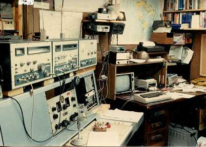
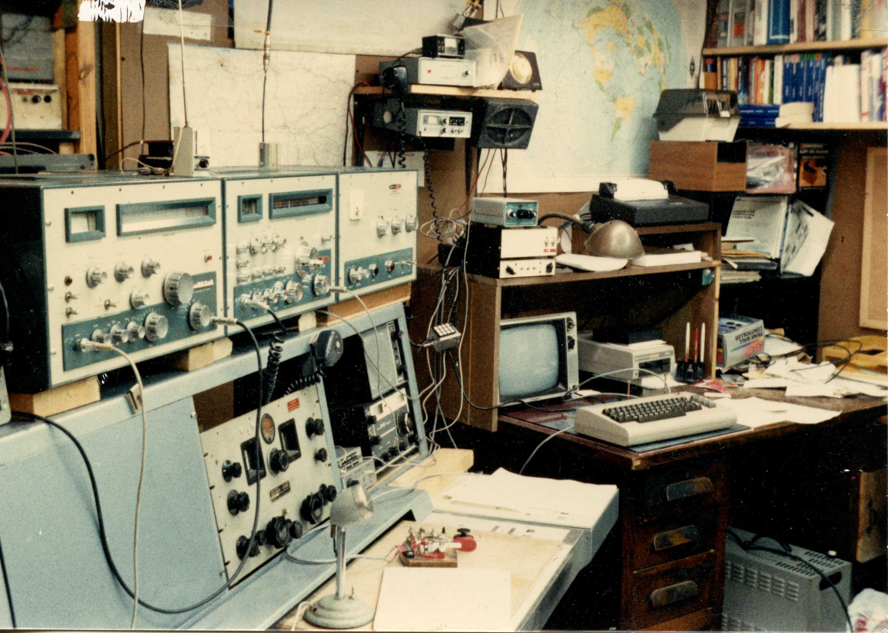
The photo on the right shows my station in 1978. Left to right, Heathkit Apache (with 160 meters), BC-779 (Hammarlund Super Pro 1.25 MHz to 40 MHz, with Product Detector), Heathkit Marauder SSB Transmitter, Drake 2C with Q multiplier, and my Commodore 64 with home brew RTTY interface. Hanging from the shelf is a Heathkit 2036 synthesized 2 meter FM with matching power supply. A home brew touch tone pad for the 2 meter rig is dangling from the 2 meter radio. There is also a Heathkit keyer and paddles mounted to a scrap of bronze from a work project. A land mobile scope and deviation meter is sitting under the desk waiting for repair. My father's desk lamp (vintage WW2) is above. There used to be an ash tray where he put his cigars, but that was lost or broken. It now has a space in W3GMS museum alongside a vintage station. The Homebrew RTTY Interface I used has its own page.
UPDATE 6/1/2015
This is a response to an email query about this article. I clarify some of the information below:
ALC
I derived ALC from the 20 ohm plate current meter. Use a resistor 2K or more to sample the ungrounded end to avoid errors in plate current measurement (this is 1% or less). I used a voltage doubler circuit to rectify it and put a pot on the back panel where the trimmer capacitor for sampling a signal for a scope was originally located. This does not save the amp from grid overdrive. That assumes the operator has not tuned the amp incorrectly, but has loaded to a full 660 mA on plate current. The transceiver drive is (pulsed) advanced to that level, maybe use some dits and a scope if you do not have a pulser to key the rig. Slowly adjust the ALC pot on the amplifier till you just see it drop a little and see the ALC meter on the exciter kick up. Switch to SSB and monitor on a scope. The rest depends on your exciter and its ALC effectiveness. Speak a spikey waveform into the mike steadily using something like "aaaaahhh". Watch the scope for flat topping. Increase the ALC output on the Warrior until the flat top disappears and the ALC peaks near whatever the MAX indication is for your transceiver. Set it there and forget it. It is not band sensitive, not sensitive to change of tubes, or any of the common problems. Correctly set, you can loudly speak and never exceed tube ratings or flat top.
WARNING: DO NOT EXCEED -4VDC ALC OUTPUT. This could damage most transceivers. Check the specs for your individual unit. A protective Zener should be installed across the ALC output to prevent this. Also, a protective high amperage schottky diode (fast, low forward drop) to ground should be installed so that the voltage cannot go positive. Some of the diodes for TV damper service might be suitable, check NTE parts for suggestions. This will never conduct except in catastrophic failure.
One failure mode possible is a shorted 811 which burns out the 20 ohm plate current sampling resistor. With Chinese tubes, this is common. Put two back to back signal diodes like 1N4148 across the panel meter in the Warrior to protect the meter.
The diodes noted in the above warning should provide some protection against this event, but nothing is foolproof. If you are nervous about this, just use the transceiver power output control and never set it for flat topping on the scope you are monitoring with. The internal power control of a modern rig is pretty good if you keep it well below the ALC max. Many wide signals heard are using NO ALC, but they punch the meter all the way to max and do not have a scope.
If you like something simpler, copy the ALC circuit in the SB200. Keep in mind that tuning and relative grid current will vary with bands and drive requirements and no one ALC setting will be perfect for all conditions. Also, if there is a plate to filaments arc, the transients will reach the transceiver in that case also. Ameritron uses arc suppressors which you can order to deal with Chinese 811s. The AL-811 and AL-572 both use them. Use TWO, one from either side of the filament. As with lightning strikes, nothing is certain protection though.
One of the reasons I use a ALS-1300 for my FT-950 now.
T/R switching details
The relays I did up for a friend were traditional 2 Radio Shack closed plastic DPDT relays rated for 10 amps and used a 12 volt DC coil. I used 2 each 12 volt AC transformers, not much current needed. I have done this several times and it works fine. Be sure to use relays with enough insulation that they will take the juice generated by a KW into 50 ohms at a 3:1 SWR. Unfortunately, Radio Shack no longer sells this relay. Possibly Mouser has a suitable relay, or you can order suitable repair stock relays from Ameritron. Mike is pretty good about supplying parts, but do your homework and give him the part number. Do not expect them to design it for you. Research their manuals and parts list for an amp using 811s. They do repairs on Heath amplifiers now though, so maybe they have just the right part figured out. The one for the SB200 will not work, since it is too high a voltage.
The primary of the first transformer wires directly across the primary of the HV transformer, so the relays cannot be activated without the plate supply being ON. Easiest place to get this is from the big bulb that indicates PLATE ON. This protects the grid circuit from ever having drive applied with the plates off (tubes destroyed instantly). The secondary 12 V is rectified and applied to the coils of both relays. Use a resistor to drop the half wave rectified voltage to 12 volts on the relays. The 12 volts is keyed via the back panel transmit/receive jack to the transceiver. Most transceivers want a positive voltage less than 12 vdc, so I put the +12v on the top of the coil and ground the lower side of the coils via the receiver contacts.
Be sure to put a diode across the relay coils which will never conduct in normal operation. The diode is wired so that it conducts if the coils generate a reverse voltage when the field collapses that energizes them. This keeps spikes out of the exciter.
RF signal path
The relay signal paths are wired so that the common contact on the first relay near the Warrior input jack goes to the exciter. The second relay common contact goes to the Warrior antenna jack. The normally closed contacts of each relay are wired together via a piece of RG58/U. When the Warrior is turned off, or the plate supply is turned off, or the station is in receive mode, the transceiver antenna signal passes directly through the amplifier. When the amplifier is activated, the grid drive wire that originally went to the input jack now goes to the normally open of the first relay, and the output wire goes to the normally open contact of the second relay. Now the transceiver goes to the grids and the Warrior output goes to the antenna.
Bias signal path
It is important to keep cutoff bias on the tubes, unless BOTH relays are closed. I used to be in aerospace industry, and we tried to protect against reasonable faults. This scheme affords a degree of protection.
The second 12v transformer has its secondary connected to the secondary of the first transformer. This causes 115 VAC to be generated by the primary, which can be used for bias. This is reverse from the normal connection, so that it is step up: this isolates the bias from direct connection to the AC line.
Half wave rectify and filter this 115VAC from the second transformer. Use a large resistance, say 100K (check wattage) to the stock Warrior bias supply as originally arranged, so that the exciter contacts were to short out the cutoff bias and provide a ground plan for the -4.5 VDC operating bias. Current is only drawn from the cutoff bias in standby mode, since AC is not present at the PLATE ON bulb.
Attach the original Warrior cutoff bias connection (ground to operate) to the unused common of the relay contacts on the input (grid) relay.
On the other (antenna) relay, wire the spare output relay common (other set of unused contacts) to ground.
Connect a wire from the normally open of the input relay to the normally open contact of the antenna relay. Leave both normally closed contacts unwired.
Trace the signal now. See that BOTH relays MUST be energized AND the PLATE supply must be ON to ground out the cutoff bias and reduce the grid voltage to -4.5VDC operating bias. This ensures that if either relay fails to activate, cutoff bias is applied, preventing tube or output tank circuit damage. The 811s will not put out much and the resting plate current will not be normal, alerting the operator to a malfunction.
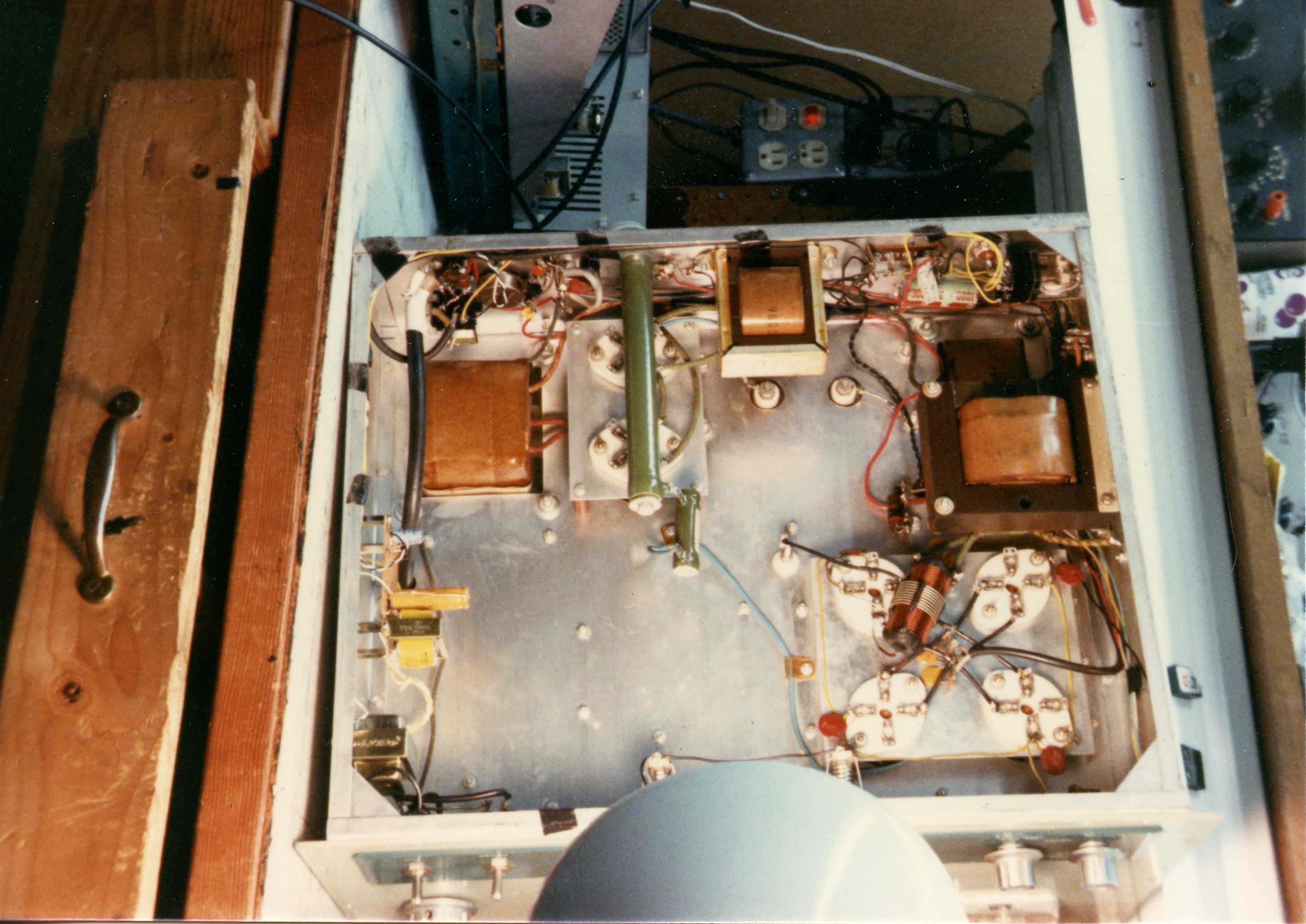
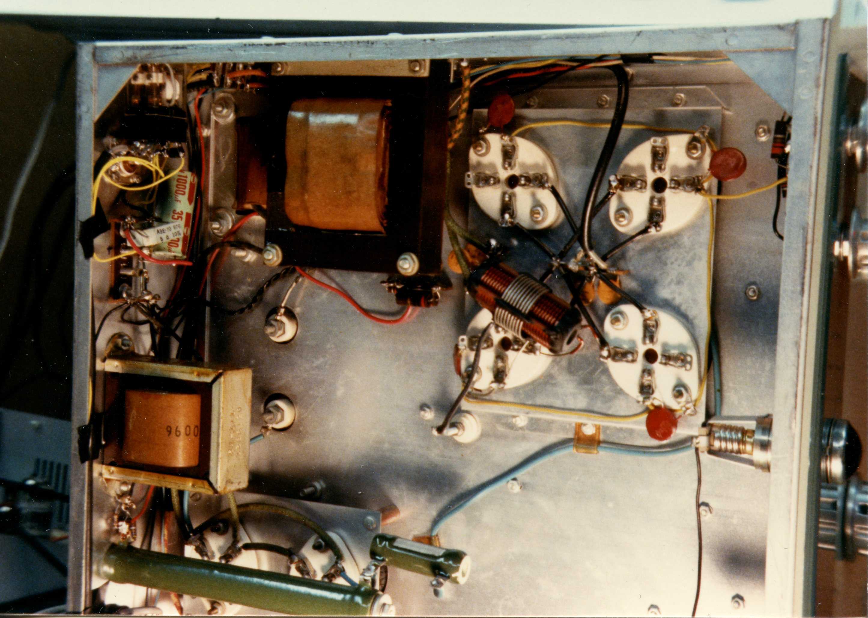
Mechanical considerations:
I fit all the power supply components on a perf board inside the Warrior on the right hand side of the chassis as viewed from the front panel. I used standoffs to mount it. The two relays can be arranged near the associated exciter and antenna connectors.
At no time is the -4.5VDC operating bias or the -100VDC cutoff bias applied to the transceiver T/R circuit.
WARNING: The coil current may exceed the rating of your transceiver. In this case, you will need to use a transistor interface like the one MFJ sells or design your own. An opto isolator is better than a transistor for protecting the transceiver.
WARNING: If your transceiver will not handle more than the relay voltage, you will need to use 6 volt relays and the center taps of the 12 VAC transformers or use an interface like MFJ sells.
WARNING: this information is provided free of charge, with no warranty or guarantee of suitability for your particular radio; you alone must be responsible for carefully measuring all parameters prior to connection to your radio or modifying your Warrior. Since I have no control over component selection or quality of workmanship, I assume no liability for damage.


|